Fluke 179 Instruction Manual: A Comprehensive Guide
This comprehensive guide details the Fluke 179 True RMS Multimeter, offering instructions for safe and effective operation. It covers features, measurements, and troubleshooting.
Explore the 28-page PDF manual, available in English, for detailed specifications, tutorials, and a thorough understanding of your Fluke 179.
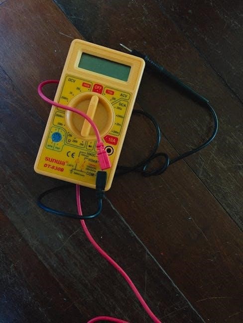
The Fluke 179, 175, and 177 models are battery-powered, true-RMS multimeters with a 6000-count display, ideal for various electrical tasks.
The Fluke 179 True RMS Multimeter represents a cornerstone of professional electrical testing, renowned for its reliability and precision. This manual serves as your guide to unlocking the full potential of this versatile instrument. Designed for electricians, technicians, and hobbyists alike, the Fluke 179 delivers accurate AC and DC voltage and current measurements.
As a battery-powered, true-RMS device, the 179 offers portability and dependable performance in diverse environments. It features a high-resolution 6000-count digital display and a responsive analog bar graph, providing clear and intuitive readings. This manual will walk you through its functions, ensuring safe and effective operation.
Included with the Fluke 179 are test leads, a 9V battery, and this comprehensive instruction manual. Some models also include a temperature probe for expanded measurement capabilities.
Key Features and Specifications
The Fluke 179 boasts a robust feature set designed for demanding electrical applications. Key features include manual and automatic ranging, providing flexibility for various measurement scenarios. It offers Display Hold and Auto Hold functions, capturing stable readings with ease. Min/Max/Average recording allows for detailed analysis of fluctuating signals.
Voltage measurements extend up to 1000V AC or DC, while current measurements reach 10A AC/DC. Frequency measurements are accurately displayed on the bar graph up to 1 kHz. The multimeter’s true-RMS capability ensures accurate readings of non-sinusoidal waveforms.
Specifications include a 6000-count display, 3 3/4-digit resolution, and a comprehensive set of measurement functions. It’s a dependable tool for professionals needing precise and reliable results.
Unboxing and Initial Setup
Upon unboxing your Fluke 179, verify the package contains the multimeter, test leads, a 9V battery (pre-installed), and the instruction manual. Some models, like the 179, include an additional temperature probe. Inspect all components for any visible damage sustained during shipping.
To begin, install the battery if it isn’t already present, ensuring correct polarity. Familiarize yourself with the input terminals and button functions as outlined in the manual. Before making any measurements, it’s recommended to perform a basic self-test to confirm functionality.
Carefully review the safety precautions detailed in the manual before powering on the device. Proper setup ensures accurate readings and safe operation of your new Fluke 179 multimeter.

Understanding the Display and Controls
The Fluke 179 features a 6000-count, 3 3/4-digit display with a bar graph, providing clear readings. Learn button functions and terminal usage for optimal performance.
Display Overview: Counts, Symbols, and Indicators
The Fluke 179’s display is a crucial component for interpreting measurements accurately. It boasts a 6000-count resolution, meaning it can display values up to 6000 digits. This high resolution allows for precise readings in various applications. The 3 3/4-digit format presents numerical values clearly and concisely.
Beyond numerical values, the display incorporates several symbols and indicators. These provide essential information about the measurement being taken, the selected range, and the instrument’s status. Indicators signal low battery, overload conditions, and input impedance. Symbols denote the measurement unit (Volts, Amps, Ohms, etc.) and the AC or DC nature of the signal.
The bar graph visually represents the signal strength, offering a quick and intuitive understanding of the measurement magnitude. It’s particularly useful for identifying rapidly changing signals or troubleshooting intermittent issues. Understanding these display elements is fundamental to effectively utilizing the Fluke 179.
Button Functions: Power, Range, Hold, etc.
The Fluke 179 features intuitive button controls for seamless operation. The Power button activates and deactivates the multimeter, conserving battery life when not in use. The Range button toggles between manual and automatic ranging, allowing users to select the desired precision or let the meter optimize sensitivity.
The Hold button freezes the current reading on the display, enabling convenient recording of measurements. Auto Hold automatically captures and displays stable readings, simplifying data logging. Min/Max/Average recording functions capture extreme values and calculate averages over time.
Additional buttons control specialized functions like relative mode, which establishes a zero baseline for comparative measurements. Familiarizing yourself with each button’s function is key to maximizing the Fluke 179’s capabilities and achieving accurate results.
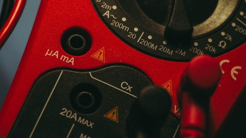
Input Terminal Descriptions
The Fluke 179’s input terminals are crucial for connecting the test leads and probes to the circuit under test. The COM (Common) terminal serves as the reference point for all measurements, typically connected to the circuit’s ground. The VΩmA terminal is used for voltage, resistance, and low-current measurements, accommodating a wide range of applications.
The 10A terminal is specifically designed for high-current measurements, capable of handling up to 10 amperes. Caution: Never connect test leads to both the VΩmA and 10A terminals simultaneously, as this can damage the meter and pose a safety hazard.
Proper connection to these terminals ensures accurate readings and safe operation. Always inspect the test leads for damage before use and ensure a secure connection to the terminals and the circuit being tested.

Basic Measurement Procedures
The Fluke 179 excels at fundamental electrical tests, including DC and AC voltage, current, resistance, and continuity. Follow these procedures for accurate results.
Ensure proper lead connections and range selection before initiating measurements, prioritizing safety and precision in every test performed.
Measuring DC Voltage
To measure DC voltage with the Fluke 179, begin by selecting the DC voltage (VDC) range on the rotary dial. Ensure the test leads are connected correctly: black to common (COM) and red to the voltage (V) terminal. Carefully connect the probes in parallel with the circuit or component under test, observing proper polarity – red probe to the positive terminal and black to the negative.
The Fluke 179 offers both manual and automatic ranging. In manual mode, select a range higher than the expected voltage. If the reading is too small or overrange, adjust the range accordingly. Automatic ranging simplifies the process, automatically selecting the appropriate range. The measured DC voltage will be displayed on the screen, along with any relevant units.
Always exercise caution when measuring voltage, especially in high-voltage circuits. Refer to the safety guidelines in the manual for detailed precautions.
Measuring AC Voltage
To measure AC voltage using the Fluke 179, rotate the rotary dial to the AC voltage (VAC) range. Confirm correct test lead connections: black to COM and red to the V terminal. Connect the probes in parallel with the AC circuit, polarity is irrelevant for AC measurements. The Fluke 179 accurately displays AC voltage up to 1 kHz on the bar graph.
Utilize either manual or automatic ranging. In manual mode, choose a range exceeding the anticipated voltage; adjust if necessary for optimal readings. Automatic ranging automatically selects the best range for convenience. The measured AC voltage will appear on the display, clearly indicating the value and units.
Remember safety precautions when working with AC voltage. Consult the manual’s safety section for comprehensive guidelines and warnings.
Measuring DC Current
To measure DC current with the Fluke 179, rotate the dial to the DC current (DCA) range. Crucially, disconnect power to the circuit before connecting the meter. Insert the red test lead into the appropriate mA or A terminal, depending on the expected current level. Connect the black lead to the COM terminal. Connect the meter in series with the circuit – break the circuit and insert the meter into the current path.
Observe polarity; incorrect connection yields a negative reading. The Fluke 179 displays DC current with appropriate units. Utilize manual or auto-ranging for optimal results. Be mindful of the meter’s current input limits to avoid damage.
Always consult the manual’s safety section before measuring current, as improper setup can be hazardous.
Measuring AC Current
To measure AC current using the Fluke 179, select the AC current (ACA) range on the rotary dial. As with DC current, disconnect power to the circuit before making connections. Insert the red test lead into the designated mA or A input terminal, appropriate for the anticipated current magnitude. Connect the black lead to the COM terminal. Remember to connect the meter in series within the circuit, breaking the current path to insert the meter.
Polarity is irrelevant for AC measurements. The Fluke 179 displays AC current with the correct units. Employ either manual or auto-ranging to achieve accurate readings. Ensure the measured current does not exceed the meter’s input limits.
Refer to the manual for safety guidelines before measuring AC current, as incorrect procedures can pose risks.

Advanced Measurement Capabilities
The Fluke 179 offers resistance, continuity, diode testing, and frequency measurements, expanding its utility beyond basic voltage and current readings for complex tasks.
Resistance Measurement
To measure resistance with the Fluke 179, ensure the circuit is de-energized to prevent damage and inaccurate readings. Select the resistance (Ω) function using the rotary dial. Insert the test leads into the appropriate input terminals – COM and the Ω input.
Apply the test leads across the component or circuit whose resistance you wish to measure. The Fluke 179 will display the resistance value on the screen, typically in ohms (Ω), kilohms (kΩ), or megohms (MΩ).
The meter supports both manual and automatic ranging for resistance measurements. In manual ranging, select the appropriate range for the expected resistance value. Automatic ranging automatically selects the best range for you. Remember to disconnect power and discharge capacitors before measuring resistance.
Continuity Testing
Continuity testing with the Fluke 179 verifies electrical connection between two points. Select the continuity function (often indicated by a diode symbol or audible beep). Insert the test leads into the COM and the diode/continuity input terminals.
Touch the test leads to the points you want to test. If a complete circuit exists (low resistance), the Fluke 179 will emit an audible tone and often display a low resistance value. An open circuit will not produce a tone or show a high resistance.
Ensure the circuit is de-energized before performing continuity tests. This function is useful for checking wires, fuses, and switch contacts. Remember to disable auto-hold during continuity testing for consistent results.
Diode Test
The Fluke 179’s diode test function assesses the functionality of diodes and other semiconductor devices. Select the diode test mode (typically indicated by a diode symbol) and connect the test leads to the COM and diode/continuity input terminals.
Apply the red lead (positive) to the anode and the black lead (negative) to the cathode of the diode. A forward-biased diode will display a voltage drop, typically between 0.5V and 0.8V. A reverse-biased diode will show “OL” (overload) on the display.
If the reading is zero or “OL” in both directions, the diode is likely faulty. Ensure the circuit is de-energized before testing. This test helps identify shorted, open, or leaky diodes within electronic circuits.
Frequency Measurement
The Fluke 179 accurately measures frequency using its dedicated frequency measurement mode. Select the frequency (Hz) function on the rotary dial and connect the test leads to the circuit under test. The meter displays the frequency in Hertz (Hz).
The bar graph accurately represents AC voltage or current up to 1 kHz when measuring frequency. Ensure the meter is set to manual range for precise frequency readings. Automatic ranging may not always provide the desired accuracy.
For signals exceeding 1 kHz, the display shows the frequency value. This function is useful for analyzing AC signals, identifying power line frequencies, and troubleshooting electronic circuits.

Special Functions and Modes
The Fluke 179 offers Auto Hold, Manual Hold, and Min/Max/Average recording for convenient data capture. Utilize these modes for efficient troubleshooting and analysis.
Auto Hold and Manual Hold
The Fluke 179’s Hold function allows you to freeze the displayed reading for later reference, crucial when working in locations where direct observation is difficult. Manual Hold requires pressing the ‘Hold’ button to capture and maintain the current value.
Auto Hold is a particularly useful feature. When enabled, the meter automatically captures and displays only stable readings, discarding fluctuating values. This simplifies measurement by eliminating the need to manually hold unstable readings, ensuring accuracy and reducing user effort.
To activate Auto Hold, access the function through the meter’s settings. The display will indicate when Auto Hold is active. Remember to disable Auto Hold when you need to view all readings, including transient signals.
Min/Max/Average Recording
The Fluke 179 offers a powerful Min/Max/Average recording function, ideal for capturing variations in measurements over time; This feature automatically records the minimum and maximum values encountered during a specified period, alongside the average reading.
To activate this mode, typically involves pressing a dedicated button or navigating through the meter’s menu. The display will then show the minimum, maximum, and average values simultaneously. This is incredibly useful for identifying intermittent issues or assessing signal stability.
This function is particularly valuable when troubleshooting circuits or monitoring fluctuating signals. It provides a comprehensive overview of measurement behavior, aiding in accurate diagnosis and analysis. Remember to reset the Min/Max/Average memory after each measurement session.
Relative Mode
The Fluke 179’s Relative mode is a valuable tool for eliminating unwanted baseline readings and focusing on changes in a signal. This function allows you to establish a new zero point, effectively subtracting the current reading from all subsequent measurements.
To engage Relative mode, typically a dedicated button is pressed after obtaining a stable initial reading. The display will then show “REL” or a similar indicator, signifying that all future readings are relative to that initial value.
This is particularly useful when measuring resistance or capacitance, where lead resistance or parasitic capacitance can introduce errors; It simplifies comparisons and highlights subtle variations, improving measurement accuracy and diagnostic capabilities.

Safety Precautions and Guidelines
Always follow general safety rules when using the Fluke 179. Ensure proper input terminal safety and handle batteries responsibly for safe operation.
General Safety Rules
Prioritize personal safety when operating the Fluke 179. Always read and understand the entire instruction manual before use, paying close attention to warnings and cautions.
Avoid using the meter in hazardous environments where flammable gases or explosive materials are present. Ensure your hands and the meter are dry to prevent electrical shock.
Never exceed the meter’s specified input limits, as this can damage the instrument and create a safety hazard. Use appropriately insulated test leads and probes, inspecting them regularly for damage.
Be cautious when working with high voltages and currents, and always disconnect power before making measurements on energized circuits. If unfamiliar with electrical safety practices, seek guidance from a qualified professional.
Input Terminal Safety
Exercise extreme caution when connecting test leads to the Fluke 179’s input terminals. Ensure the meter is switched off before making or breaking connections to prevent accidental shorts or electrical shock.
Always use the correct input terminals for the type of measurement being performed – voltage, current, resistance, etc. Incorrect connections can damage the meter and pose a safety risk.
Never attempt to measure voltages or currents exceeding the meter’s specified maximum ratings. This can lead to damage and potential injury. Inspect test leads for insulation damage before each use.
Avoid touching exposed metal parts of test leads while the meter is connected to a live circuit. Properly insulate connections to minimize the risk of accidental contact.
Battery Safety
The Fluke 179 utilizes a 9V battery for operation. When replacing the battery, always ensure the meter is switched off to prevent electrical shock or damage to the instrument.
Dispose of used batteries responsibly, following local regulations for battery recycling or disposal. Do not incinerate batteries, as they may explode or leak hazardous materials.
Avoid short-circuiting the battery terminals. This can generate heat and potentially cause burns or damage to the meter. Use insulated tools when handling batteries.
Ensure correct battery polarity during installation. Incorrect polarity can damage the meter’s circuitry. Only use a standard 9V alkaline battery for optimal performance.

Maintenance and Troubleshooting
Regular cleaning and proper storage ensure longevity. Address common issues like display problems or inaccurate readings with the troubleshooting guide provided in the manual.
Battery Replacement
The Fluke 179 operates on a standard 9V battery. When the low battery indicator appears on the display, promptly replace it to maintain accurate measurements and reliable performance.
To access the battery compartment, locate the battery cover on the rear of the multimeter. Unscrew the cover and carefully remove the old battery.
Install a fresh 9V battery, ensuring correct polarity as indicated inside the compartment. Securely replace the battery cover and tighten the screw.
Dispose of used batteries responsibly, following local regulations for battery recycling. Incorrect battery disposal can harm the environment. Always use a high-quality 9V battery for optimal results.
Cleaning and Storage
To maintain your Fluke 179’s performance and longevity, regular cleaning is essential. Periodically wipe the exterior with a damp cloth, avoiding abrasive cleaners or solvents that could damage the casing or display.
Disconnect test leads before cleaning. Ensure the multimeter is powered off. For stubborn grime, use a mild soap solution, followed by a clean, dry cloth.
When storing the Fluke 179, choose a dry, dust-free environment. Avoid extreme temperatures or humidity. The included carrying case provides excellent protection during transport and storage.
Remove the battery for extended storage to prevent potential corrosion or leakage. Proper cleaning and storage will ensure your Fluke 179 remains a reliable tool for years to come.
Common Issues and Solutions
If your Fluke 179 displays “OL” (Overload), it indicates the selected range is insufficient for the measured value. Switch to a higher range or use the auto-ranging function.
A blank display often signals a dead battery. Replace the 9V battery with a fresh one. Ensure correct polarity during installation.
Inaccurate readings can stem from damaged test leads. Inspect leads for breaks or corrosion and replace them if necessary. Verify proper connection to the circuit.
If the meter fails to respond, check the battery and fuse. Modern Fluke multimeters lack publicly available schematics for in-depth repair.
Fluke 179 Accessories
The Fluke 179 includes test leads, a 9V battery, and a manual. An optional temperature probe is also available for expanded measurement capabilities.
Explore additional Fluke accessories to enhance your multimeter’s functionality and address specific testing requirements effectively.
Included Accessories
Upon unboxing your Fluke 179 True RMS Multimeter, you’ll find several essential components to get you started immediately. These included accessories are designed to ensure accurate and safe measurements right out of the box;
First and foremost, a set of high-quality test leads is provided, enabling you to connect the multimeter to the circuit or component under test. These leads are typically color-coded for easy identification of polarity.

A 9-volt battery is also included, pre-installed within the multimeter, providing the necessary power for operation. This ensures the device is ready for use without requiring an immediate battery purchase.
Finally, and crucially, a comprehensive instruction manual accompanies the Fluke 179. This manual details all features, functions, safety precautions, and troubleshooting steps, guiding you through every aspect of using your new multimeter.
For the Fluke 179 specifically, a temperature probe is often bundled, expanding its measurement capabilities beyond standard electrical parameters.
Optional Accessories
While the Fluke 179 comes equipped with essential accessories, expanding its functionality is possible with a range of optional additions. These accessories cater to specialized measurement needs and enhance the multimeter’s versatility.
Various probe kits are available, including specialized probes for temperature, AC current, and high-voltage measurements. These probes offer increased accuracy and safety in specific applications.
A carrying case provides robust protection for your Fluke 179 during transport and storage, safeguarding it from physical damage and environmental factors.
Different sets of test leads with varying lengths, connectors, and features, such as retractable leads or alligator clips, can improve convenience and accessibility;
Consider a Fluke link for wireless data logging and remote monitoring, enabling you to capture and analyze measurements over time without direct connection.